Well its time for post 3 on my Mandolin Project . I ended the last post with a contraption I had assembled and asked for guesses as to what it was for. Sadly I got no response . The unit was made to bend Hard Maple wood. If you look closely at the picture there is a Torch pointed into the pipe . The pipe bent on an angle in the vise and the vise mounted solidly to a table.
This was the part that scared me the most and turned out to be the most fun. I cut my Hard Maple sides to the approx size I wanted ( slightly over Size) Then I put them in a PVC Tube I have glued an end on and filled it with water , closed the top so that the wood was completely submerged for a day .
The wood has to be quite soaked. I then took the individual pieces out and fired up the torch , as the pipe got hot , I rolled the wood pieces back and forth over the pipe applying SLIGHT PRESSURE.
This is the hardest part, as the wood begins to steam , I lifted it up and continued spraying the back of the wood with water to keep it wet . It started getting
ply able and the first reaction is to press harder BAD MOVE . IT WILL BREAK ! I went through 5 pieces to get 3 Bent as I needed.

After an experiment , and a broke piece , my first part was ready for the mold. As you can see I have made a Plywood Mold from my pattern I showed in post 1. Clamp the part in place and let it set for 24 hours . As the wood drys out it will retain what ever shape you have it molded into .

I strongly recommend the plastic footed claps as you see below , the Quick Grip Type . The others will leave marks that are very hard to sand out , as I discovered the hard way .

After the bending and shaping was done I moved to an Internal Mold as shown below to fit the parts together . I have said they will hold their shape,
that's true to about 98% there is slight movement or was on my unit. As you can see I have also put the Tail Piece and Head Piece in to fit the sides to here

These parts are being Glued into place in this Jig at this point , so that when its done you have the outer ring made up of the 1/8" side parts as well as the Tail Piece and Head Stock.

After the Sides and Ends have been glued together I started
Gluing the "
Kerfing " into place . This material is slotted to bend to the shape your making nicely and is glued in a approximately 1/64" below the surface of the edges . I did this on purpose so that after I had the
unit Glued up , I could run it through my Sander and make sure it was Level and flat prior to working on the back.

I suspect most will have the unit in the Jigs until the back is glued in place . I however chose to allow the sides to expand and move to the exact figure that the bends took them to and then applied it to the back. This was a choice I made to let any stress that had been created from the above
gluing to be relieved . Good / Bad I
don't know , however it did seem to work

If you are going to allow the stress to relieve as I did DO NOT notch the head
piece prior to this because then the alignment may be slightly off. It does make the notching a bit harder , however I felt the possibility of
relieving as much stress as possible was good on my first attempt.
The Next post will involve shaping and
gluing the back and internal supports
Thank You for stopping by and following my little project
 I made a pearl pick guard from a sheet I purchased from Stewart MacDonald and since I didn't want it actually touching the top surface I purchase the smallest rubber O rings I could find and put 1 under each screw so the pick guard is approx 1/16" off the top surface.
 You can see parts of the Label in the pic through the sound hole . It says " WudWerks Inc. Serial # 0001 Manuf Date 7-9-09"
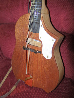

 The following picture shows the head being laminated around the sides with the Mahogany to match the stripes in the neck and the top. Notice the fine precision clamping mechanisms that are keeping
  After that was glued and trimmed I finally was able to do some assembly I have screwed in the tail piece and the Tuning pegs in the head . I set the bridge in place and put strings on it. I wanted to see how well the sound was at this point before I started the Lacquer. If sanding was needed now is the time to do it. As you can see through the sound hole , one of my braces is
  The unit is tuned and checked for sound. I have spent a little extra and purchased the better quality tuning pegs and tail piece in a polished brass . The tuning keys have pearl knobs. Notice the location of the ebony bridge in relation to the sound hole . Remember I said earlier in a post the distance from the fret with the (2 ) pearl inlay dots to the nut ( bone piece at head ) is approx same
  The sound is actually quite good considering its my first attempt at a mandolin. I am rather happy at this point and quite relieved. Time for
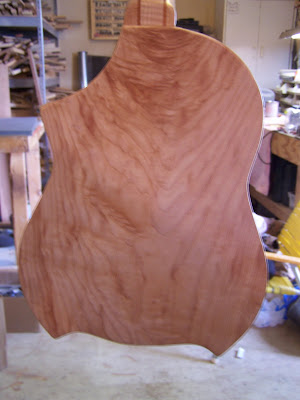


 Each Fret wire is cut over sized and hammered into the
  In the Pic below I have drilled and glued in the pearl inlay dots I chose for my fret board. These are set in the center of the # 3 / 5 / 7 / 10 / 12 / 15 frets . You will notice the 12
 In the pic below I have fitted the fret board to the neck of my Mandolin and have it glued in place . To the left end you can see the
  The below pic shows the Bridge that set at the back of the Mandolin and holds the string spacing properly. The distance from the " Nut" of the Mandolin ( the white bone glued in the neck at
 The below pic shows the unit
  In the next pic I have made the tension rod cover from the
 If you look closely you can see the notched "
 Also you can see in the above pic that I have cut the headstock to receive the "Tang" from the neck to create a solid joint. The back is solid an the tang sits down and is glued to the back as well as the insides to make a solid joint.
 I place 3 across , and learned that two would have been enough probably . Oh well next time.
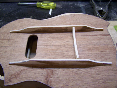
 Below You can see I have glued the neck into place . Why I
  You can see the top being glued in and the neck set . If you look closely you will see the Hard Maple strip in the neck I glued in to cover the Tension Rod.